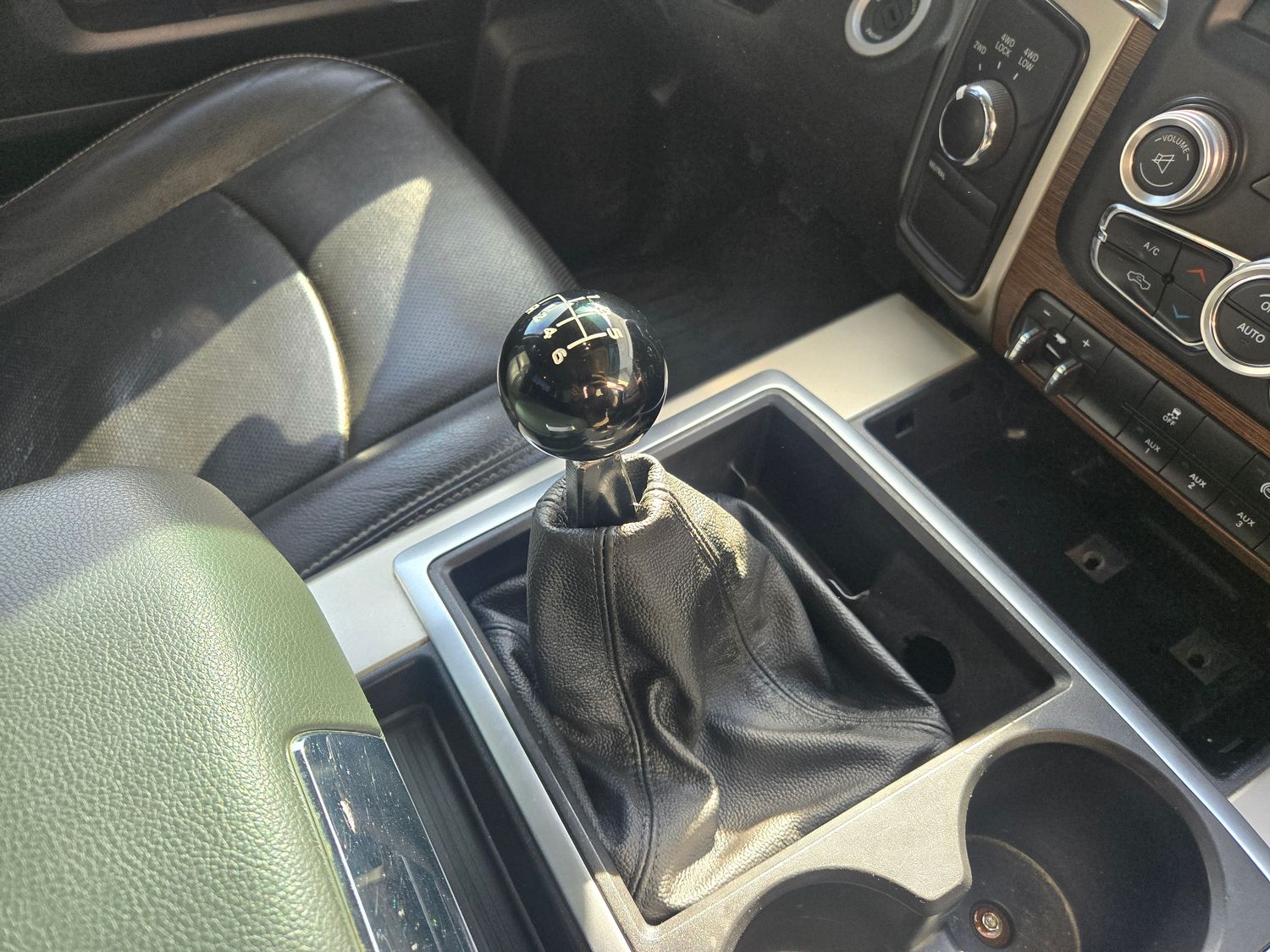
Business Center Console Remote Shifter Kit for G56 Transmissions Dodge Ram 6.7l Cummins
Part Number: KB-G56-RSK
$289.95
Add Shifter Ball?
Add Leather Boot?
When Will My Item Arrive?
Shipping: 3–7 days
In stock
1
Business Center Console Remote Shifter Kit for G56 Transmissions Dodge Ram 6.7l Cummins
Product Details
Cross Reference:: Remote Shifter Shift Tower Shift Stud NV3500 NV4500
Includes:
Transmission stud adapter
Linkage arm
Floor bracket
Remote shifter arm w/ M10-1.5 threaded shifter stud
Heim joint
Mounting hardware
Options:
Shifter ball (G56 Pattern)
Leather shifter boot
Fits: 4th Gen Ram Trucks with Business Center Console and G56 Transmission.
*We have not attempted to use this with a short throw shift tower. It may or may not work.
Assembly Instructions:
- This kit requires gutting and trimming the inside of the center console. The instructions will not cover either of these steps. Please refer to some of our pictures for a rough idea of what is cut away.
- Bolt the transmission adapter onto the shift tower with the two M8 bolts and nuts. The adapter should bolt to the LH side of the OE shift tower.
- Assemble the new shifter using one jamb nut and one heim joint. The jamb nut and heim joint should be threaded all the way onto the shifter. Tighten the jamb nut onto the heim joint to lock it in place. (This can be adjusted later)
- Install the floor bracket using one existing OEM bolt and two supplied 1/4" self tapping screws. The long slot will be on the passenger side. The two 1/4" self tapping screws should be used on the long slot. Place them so there is some adjustment right to left. A good place to start is about 3/8" of the slot showing on the drivers side after the factory bolt has been installed.
- Assemble the shifter onto the floor bracket using the bottom most hole. Use the long 1/2" bolt, two heim joint spacers (one on each side of the heim joint) and two washers. The floor bracket will rise on the passenger side of the shifter. So from the passenger side to the drivers side the bolt should have: Washer, floor bracket, cone spacer, heim joint, cone spacer, washer, nut.
- Using the two short 1/2" bolts and nuts, install the linkage using the middle hole on the shifter. Be sure to lubricate the faces and holes of the linkage with grease. Blue thread locking compound on the nuts is recommended but wait until final assembly to apply.
- Check for shifter clearance. You may need to adjust the floor bracket left to right. If the bracket cannot be cheated enough using the slots then washers can be used on the 1/2" bolt to space the heim joint towards the drivers side. This will help avoid unnecessary holes in the floor.
- Adjustments of linkage: Using the highest hole on the shifter will decrease throw. Using the lowest hole will increase throw. The shifter linkage is designed for use with the middle hole although we left the top and bottom holes to allow for some customizing if desired.
- Once you are happy with the set up of the shifter and linkage don't forget to apply thread locking compound to the linkage nuts.
- Install the shifter boot by trimming the tray. Any type of ~1/8" thick plastic (not included) can be used to sandwich the shifter boot to the plastic on the inside of the cup holder. The layers go, plastic cup holder, shift boot, plastic. Fasten with short self tapping screws of a large diameter from the inside out. Now cut or grind the excess length of the screws sticking out where the cup holder tray slides into the console.
- The top of the shift boot can be tucked into itself for a better finished look. A few threads may need to be pulled depending where you want the boot to sit. Electrical tape can be used on the inside of the shifter to prevent the boot from sliding down too far. Or if you prefer the boot can be taped to the shifter on the underside after folding the top in.
You May Also Like
Display prices in:USD
